Correctly connecting a three-phase asynchronous motor starts with one rule: read the motor nameplate before changing any terminal links.
Three-phase motors commonly use star (Y) or delta (Δ) winding connections, but the correct connection is determined mainly by the motor's rated winding voltage and the available line voltage—not simply by motor power.
For example, on a 400V three-phase supply:

Both motors may have six terminals and appear very similar, but connecting them incorrectly can apply excessive voltage to the windings or prevent the motor from producing its rated output.
This guide explains how three-phase motor wiring works, how to identify U1, V1, W1, U2, V2 and W2 terminals, when to use star or delta connection, how star-delta starting differs from normal wiring, and how to troubleshoot common connection problems.
Three-phase motor wiring involves hazardous voltages. Installation, testing and modifications should be performed by qualified electrical personnel with the power isolated and applicable electrical safety procedures followed.
How Does a Three-Phase Asynchronous Motor Work?
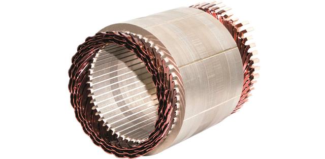
A three-phase asynchronous motor, also called a three-phase induction motor, uses three stator windings supplied by three-phase AC power.
The three currents are electrically displaced from one another and create a rotating magnetic field inside the stator.
This rotating magnetic field induces current in the rotor, creating electromagnetic torque that causes the rotor to turn.
The rotor operates slightly slower than the synchronous magnetic field. This speed difference is called slip and is necessary for an induction motor to produce torque.

Why the Winding Connection Matters
Each stator phase winding is designed for a specific voltage.
The star or delta connection determines how much of the line-to-line supply voltage appears across each individual winding.
If the wrong connection is used, the winding may receive either:
Too much voltage
Too little voltage
Both conditions can cause operating problems.
Excessive winding voltage can cause high current, overheating and winding damage.
Insufficient winding voltage can significantly reduce available motor torque.
What Is Star and Delta Connection?
Most IEC three-phase motors with six accessible terminals can connect their three stator windings in either:
The motor terminal box commonly contains six terminals:
U1 – V1 – W1
U2 – V2 – W2
These represent the beginning and end of the three phase windings.
Star Connection
In a star connection, one end of each winding is connected together to form a common point.
The other three winding ends connect to the three supply phases.
![Y接法]()
With the common IEC terminal arrangement, the incoming phases normally connect to:
and:
are linked together.
Delta Connection
In a delta connection, the end of each winding connects to the beginning of another winding, forming a closed triangular circuit.
For a typical IEC six-terminal motor, the three winding pairs are connected according to the manufacturer's terminal diagram.
![三角形接法]()
Depending on the terminal block physical arrangement, bridging may connect combinations such as:
Always follow the wiring diagram supplied with the motor because terminal layouts can vary.
Star vs Delta: Understanding the Voltage Difference
The relationship between line voltage and winding voltage is the key to understanding three-phase motor wiring.
![接线方法]()
Voltage in Star Connection
In star:
Winding Voltage = Line Voltage ÷ √3
For a 400V three-phase supply:
400 ÷ 1.732 ≈ 230V
Therefore, each motor winding receives approximately 230V.
This is why a motor marked:
230/400V Δ/Y
operates in star when connected to a 400V power supply.
Voltage in Delta Connection
In delta:
Winding Voltage = Line Voltage
If the supply is 400V, each winding receives the full 400V.
Therefore, a motor with windings designed for approximately 400V may be marked:
400/690V Δ/Y
and operate in delta on a 400V supply.
How to Read Δ/Y Voltage on a Three-Phase Motor Nameplate
This is the most important part of motor connection selection.
![nameplate]()
If the nameplate shows two voltages such as:
230/400V Δ/Y
the first voltage corresponds to delta and the second corresponds to star.
Likewise:
400/690V Δ/Y
means:
Example 1: 230/400V Δ/Y Motor
For a motor marked:
230/400V Δ/Y
use approximately:
230V supply → Delta
400V supply → Star
Why?
Because the individual winding is designed for approximately 230V.
On 400V line voltage in star:
400 ÷ √3 ≈ 230V per winding
Example 2: 400/690V Δ/Y Motor
For:
400/690V Δ/Y
use approximately:
400V supply → Delta
690V supply → Star
The winding itself is designed for approximately 400V.
On a 400V supply, delta places 400V directly across each winding.
Example 3: 220/380V Δ/Y Motor
A 220/380V motor follows the same principle:
This type of rating is common in markets using approximately 380V three-phase supplies.
Example 4: 380/660V Δ/Y Motor
For a motor marked:
380/660V Δ/Y
the correct connections are approximately:
This distinction is particularly important because both a 220/380V motor and a 380/660V motor may operate in a factory with a 380V supply—but they require different connections.
| Motor Nameplate | Supply Voltage | Connection |
220/380V Δ/Y | 220V | Delta |
220/380V Δ/Y | 380V | Star |
230/400V Δ/Y | 230V | Delta |
230/400V Δ/Y | 400V | Star |
380/660V Δ/Y | 380V | Delta |
380/660V Δ/Y | 660V | Star |
400/690V Δ/Y | 400V | Delta |
400/690V Δ/Y | 690V | Star |
Always use the actual nameplate information supplied with the specific motor.
Does Motor Power Determine Star or Delta Connection?
No.
This is a common misunderstanding.
A rule such as:
“Small motors use star and large motors use delta”
is not technically sufficient.
Motor power does not independently determine the running connection.
The correct running connection is primarily determined by:
Why Are Small Motors Often Seen in Star?
Some manufacturers design smaller motors for 230/400V Δ/Y, making star the normal running connection on a 400V European supply.
Larger motors may instead use 400/690V Δ/Y windings and therefore operate in delta on the same 400V supply.
This can make it appear that the connection is based on motor power.
In reality, the difference comes from the winding design and rated voltage.
Three-Phase Motor Terminal Wiring
Most IEC motors capable of star and delta connection have six terminals.
Common terminal designations are:
Typical Star Wiring
A typical star connection has:
Supply:
Linked together:
This creates the star point.
Typical Delta Wiring
In a typical delta arrangement, each winding end connects to the beginning of the next phase.
One common IEC connection is:
U1 linked to W2
V1 linked to U2
W1 linked to V2
The three line phases connect to these three junctions.
Do Not Rely Only on Bridge Orientation
Some motor terminal boards are physically arranged differently.
Therefore, do not assume:
Horizontal bridges always mean one connection and vertical bridges always mean another.
Use the motor terminal diagram and terminal markings.
How to Reverse the Rotation of a Three-Phase Motor
The rotation direction of a standard three-phase induction motor is determined by phase sequence.
To reverse rotation, interchange any two incoming supply phases.
For example:
Original:
Reverse two phases:
The rotating magnetic field reverses direction, causing the motor to rotate in the opposite direction.
Check the Driven Equipment Before Reversing
Some machinery must operate in only one direction.
Examples include:
Pumps
Fans
Screw conveyors
Compressors
Gearboxes with backstops
Always confirm the required rotation before prolonged operation.
Star Connection vs Star-Delta Starting
A very important distinction is:
Star connection for normal operation is not the same as star-delta starting.
Normal Star Connection
A 230/400V Δ/Y motor operating on a 400V network normally runs permanently in star.
It is not necessarily being “star-delta started.”
What Is Star-Delta Starting?
Star-delta starting is a reduced-voltage starting method.
The motor:
Starts with its windings connected in star.
Accelerates toward operating speed.
Switches to delta for normal running.
The star connection reduces the voltage applied to each winding during starting.
Which Motor Can Use Star-Delta Starting?
The motor must be designed to run in delta at the available supply voltage.
For example, on a 400V supply:
A:
400/690V Δ/Y motor
can normally run in delta at 400V and may therefore be suitable for star-delta starting, subject to the application and starter design.
A:
230/400V Δ/Y motor
normally runs in star at 400V.
It should not simply be switched to delta on a 400V network because each 230V-rated winding would then receive approximately 400V.
Star-Delta Starting and Torque
During star starting, winding voltage is reduced.
As a result, starting current is reduced, but starting torque is also significantly reduced compared with direct delta starting.
Therefore, star-delta starting is most suitable when the load can accelerate with reduced starting torque.
Applications Requiring High Starting Torque
Applications such as:
may not accelerate successfully using a conventional star-delta starter.
A VFD or soft starter may offer better control depending on the application.
Star vs Delta: Does One Use More Energy?
It is misleading to say that star connection automatically “saves energy” while delta connection “uses more energy.”
The correct connection allows each winding to operate at its designed voltage.
A 230/400V motor running in star on 400V is operating normally.
A 400/690V motor running in delta on 400V is also operating normally.
Neither connection is inherently a general-purpose energy-saving mode.
What Determines Motor Energy Efficiency?
Energy efficiency depends on factors such as:
For energy-saving projects, select an appropriately sized IE3 or IE4 motor and operate it close to its efficient load range rather than changing star/delta connections without considering the winding rating.
What Happens If a Motor Is Connected Incorrectly?
Incorrect three-phase motor wiring can produce serious problems.
Connecting a 230/400V Motor in Delta on 400V
Each winding would receive approximately 400V even though it is designed for about 230V.
Possible results include:
Connecting a 400/690V Motor in Star on 400V for Normal Full-Load Operation
Each winding receives only:
400 ÷ √3 ≈ 230V
instead of approximately 400V.
The motor may run at light load, but available torque is greatly reduced.
Possible symptoms include:
How to Connect a Three-Phase Motor Safely
Actual motor connection work should be carried out by qualified personnel.
A professional installation normally includes the following checks.
Step 1: Check the Motor Nameplate
Verify:
Rated voltage
Frequency
Rated current
Power
Δ/Y connection
Rated speed
Duty
IP rating
Step 2: Verify the Supply
Measure and confirm:
Line voltage
Frequency
Phase availability
Phase balance
The supply must match the motor rating.
Step 3: Identify the Motor Terminals
Confirm U1, V1, W1, U2, V2 and W2 according to the manufacturer's wiring diagram.
Step 4: Install the Correct Links
Use star or delta links according to the nameplate voltage and power supply.
Step 5: Connect Protective Earth
The motor frame must be correctly grounded according to applicable electrical requirements.
Step 6: Set Motor Protection
Motor protection equipment should be set according to the correct rated current and connection configuration.
Step 7: Check Rotation
After safe commissioning, verify the rotation direction before coupling the motor to equipment where incorrect rotation may cause damage.
What About 9-Lead and 12-Lead Three-Phase Motors?
Not every three-phase motor uses the IEC six-terminal arrangement.
![三电压]()
Some motors—particularly motors designed for different international markets—may have:
A typical North American 230/460V motor, for example, may use a nine-lead series/parallel connection instead of the six-terminal Δ/Y arrangement discussed above.
Therefore:
Do not apply a six-terminal IEC star/delta wiring diagram to a nine- or twelve-lead motor.
Always use the motor-specific connection diagram.
Common Three-Phase Motor Wiring Problems
Motor Does Not Start
Possible causes include:
Motor Runs but Has Very Low Torque
Check whether a motor designed to run in delta has accidentally been left connected in star.
Also check:
Supply voltage
Phase imbalance
Mechanical overload
Incorrect frequency
Motor Overheats Quickly
Possible causes include:
Motor Rotates in the Wrong Direction
Interchange any two incoming supply phases after isolating the supply and following proper electrical procedures.
Three-Phase Motor Wiring with a VFD
When a motor is powered through a Variable Frequency Drive, follow the VFD and motor manufacturers' voltage and connection requirements.
For example, a VFD outputting approximately 400V normally requires the motor to be configured for its correct 400V operating connection.
![变频器连电机]()
The VFD controls:
Frequency
Output voltage
Acceleration
Deceleration
Motor speed
It does not make an incorrect winding connection safe.
Do Not Switch Star and Delta on the VFD Output While Running
Contactors should not normally switch motor winding connections on the live output side of a VFD unless the drive system has been specifically engineered for that purpose.
For normal VFD applications, the motor is connected in the appropriate fixed configuration.
How Victory Supports Three-Phase Motor Connection and Selection
Victory Machinery Technology Co., Ltd. supplies three-phase induction motors for OEM manufacturers, industrial distributors, maintenance companies and end users.
Because voltage and winding configuration vary between markets, Victory can select the motor winding according to the customer's actual power system.
![微信图片_20250912094428_154_7]()
Common Voltage and Frequency Options
Depending on motor design and project requirements, configurations may include:
220/380V 50Hz
230/400V 50Hz
380/660V 50Hz
400/690V 50Hz
415V 50Hz
220/440V 60Hz
230/460V 60Hz
440V 60Hz
480V 60Hz
The exact winding and terminal arrangement should always be confirmed for the specific motor.
Motor Options
Victory can provide:
OEM and Replacement Motor Support
![11]()
For replacement projects, Victory can evaluate:
Electrical parameters
Voltage and frequency
Rated current
Pole count
Rated speed
Frame size
Mounting
Shaft dimensions
Flange dimensions
Terminal box position
This is particularly important when replacing an existing motor from another brand because matching only power and voltage may not be sufficient.
FAQ About Three-Phase Motor Wiring
How Do I Know Whether to Connect a Motor in Star or Delta?
Read the motor nameplate.
For a motor marked 230/400V Δ/Y, approximately 230V uses delta and 400V uses star.
For 400/690V Δ/Y, approximately 400V uses delta and 690V uses star.
Does a 3 kW Motor Always Use Star Connection?
No. Motor power alone does not determine star or delta connection. The correct connection depends on the winding voltage and supply voltage.
What Does 400/690V Δ/Y Mean?
It normally means the motor is rated for approximately 400V when connected in delta and 690V when connected in star.
What Does 230/400V Δ/Y Mean?
It means the motor normally operates in delta at approximately 230V and star at approximately 400V.
Can a 230/400V Motor Use Star-Delta Starting on a 400V Supply?
Normally no. It already needs to run in star at 400V. Switching it to delta would place approximately 400V across windings designed for about 230V.
Which Motor Can Use Star-Delta Starting on a 400V Supply?
A motor designed to run in delta at approximately 400V, such as a suitable 400/690V Δ/Y motor, may be used with star-delta starting if the application can accelerate with the reduced starting torque.
How Do I Reverse a Three-Phase Motor?
Interchange any two incoming supply phases. This reverses the phase sequence and therefore the direction of the rotating magnetic field.
Why Does My Motor Run in Star but Fail Under Load?
If the motor is designed for delta operation at the available line voltage, leaving it in star reduces winding voltage and available torque. Check the nameplate and connection diagram.
Can I Use the Same Wiring Diagram for a 9-Lead Motor?
No. Nine-lead and twelve-lead motors may use different series/parallel winding arrangements. Follow the specific motor wiring diagram.
Conclusion
Correct three-phase motor wiring is determined primarily by the relationship between the motor winding voltage and the available supply voltage.
The key rule is to read the nameplate:
230/400V Δ/Y → 230V Delta, 400V Star
400/690V Δ/Y → 400V Delta, 690V Star
220/380V Δ/Y → 220V Delta, 380V Star
380/660V Δ/Y → 380V Delta, 660V Star
Motor power alone does not determine whether the motor should run in star or delta.
It is also important to distinguish a permanent star connection from star-delta starting. A star-delta starter temporarily reduces winding voltage during acceleration and then switches the motor to its normal delta running connection.
Incorrect connection can cause insufficient torque, excessive current, overheating or winding damage.
Before connecting or replacing a three-phase asynchronous motor, verify the nameplate, supply voltage, frequency, terminal arrangement, rated current and application requirements.
Victory can provide three-phase motors with different voltage, frequency, pole, efficiency and terminal configurations and can support OEM and replacement projects with electrical data, connection diagrams and dimensional matching.